Unknown's avatar

FPGA based IBM-PC-XT


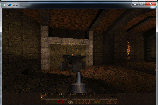
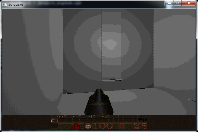
Recently I undertook a hobby project to recreate an IBM XT Personal Computer from the 1980s using a mix of authentic parts and modern technology. I had a clear goal in mind: I wanted to be able to play the EGA version of Monkey Island 1 on it, with no features missing. This means I need mouse support, hard drive with write access for saving the game, and Adlib audio, my preferred version of the game’s musical score.

The catalyst for this project was the discovery that there are low-power versions of the NEC V20 CPU available (UPD70108H), which is compatible with the Intel 8088 used in the XT. Being a low-power version significantly simplifies its connection to an FPGA, which typically operate with 3.3-volt IO voltages. Coupled with a low-power 1MB SRAM chip (CY62158EV30) to provide the XT with its 640KB of memory, and I started to have the bones of a complete system worked out.

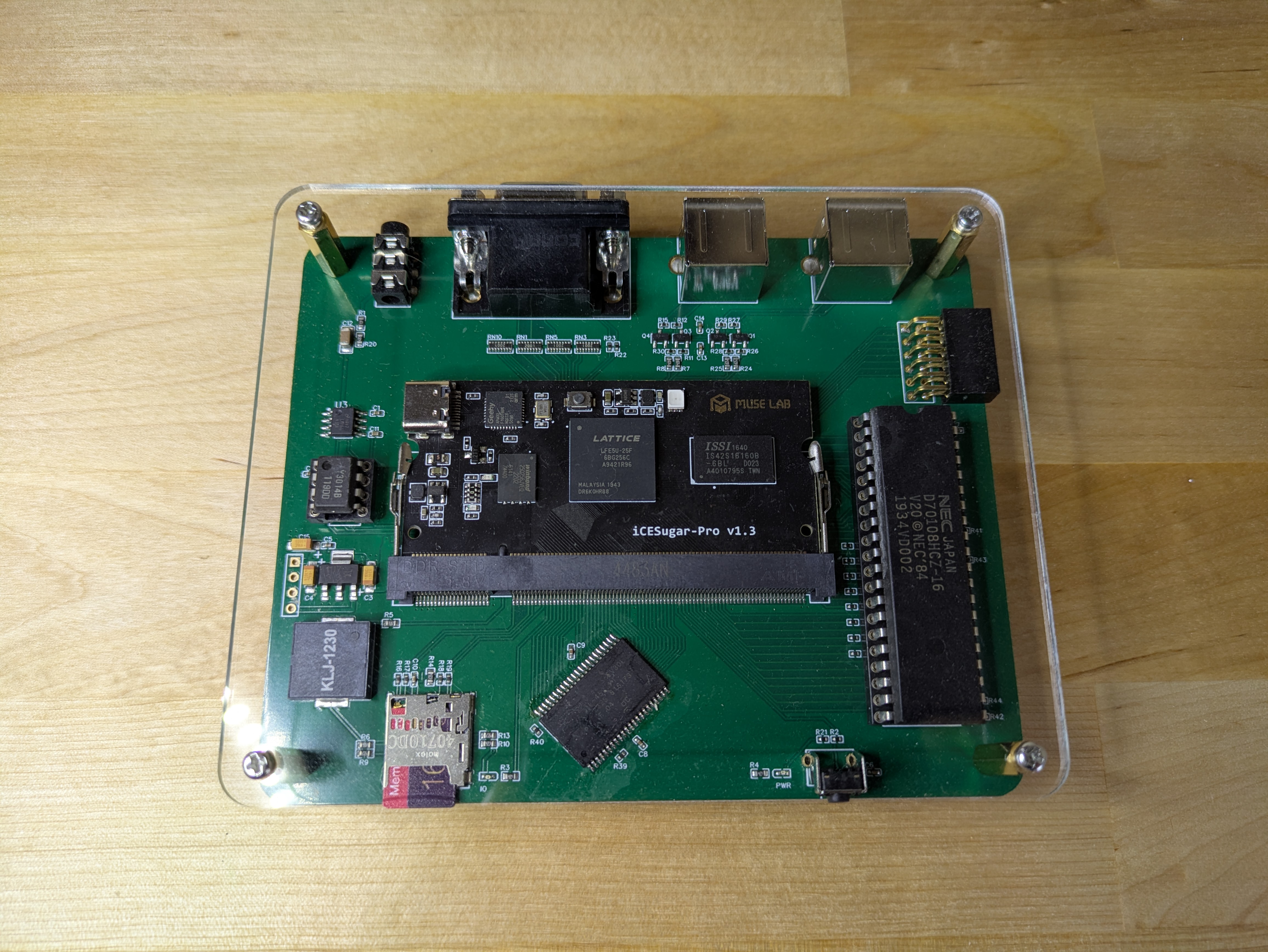
I started off by designing the hardware of the system, which would then serve as my development board while I worked on the software/gateware. The following features were added:
– DIP-40 socket for an low power NEC V20 CPU
– 1MB SRAM chip for the system memory
– An icesugar-pro FPGA board with a Lattice LFE5U-25F
– Dual PS/2 connectors for keyboard and mouse
– Micro SD card socket to act as a Fixed Disk
– An authentic YM3014B digital-to-analogue converter for audio
– A Piezo speaker that can be driven by the programmable-interval-timer for system bleeps
– Lastly, a reset switch and some status LEDs


I drew up my design using the EasyEDA CAD software as I’m already familiar with it, and it has really good integration with the JLCPCB PCB assembly service. Some of the components in the design are too tricky for me to hand solder by myself. I did however have to solder the SRAM chips once the boards arrived since they were not stocked by LCSC so I had to source them elsewhere.


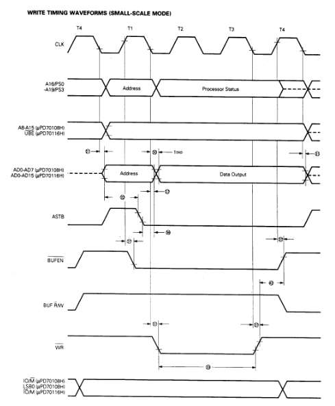
The first step was to write a bus controller for the processor. The V20 CPU clock is more forgiving than an original i8088 since its can be run right down to 0hz and its uses a regular 50% duty cycle. The external interface for an 8088 CPU operates in terms of bus cycles. At that start of a bus cycle the CPU asserts some pins to let everyone know what it wants to try and do… read memory, write to IO, etc. Each type of bus cycle follows a specific sequence of events that happen over a number of clock cycles. It was straight forward to make a state machine that could detect the start of a bus-cycle, figure out what kind it was, and then produce or consume the data as needed by the CPU. Key here, was to make sure that all of the timing requirements were met, so that signals the CPU generates are sampled at the correct time, and signals the CPU requires have been driven correctly before the CPU reads them.

An example memory write bus cycle timing diagram.

My first test for the bus controller was to write a simple program using NASM to be executed on the V20, with a simple goal… it will flash an LED mapped to an IO port address. Simple, but a blinking LED seems to be the hardware equivalent of the software hello-world. For the initial version, the program was simply loaded into a FPGA block ram and used directly as the system memory.

Later, I used a more complex approach for memory accesses. The bios, for example, is loaded into an FPGA block ram, so that CPU memory reads will come from that rather than the system SRAM chip. Video memory is implemented a differently still. CPU memory writes are passed to both the video memory block ram and system SRAM, but CPU reads alway come from only the system SRAM. This then means that I have a spare read port on the video block ram that can then be used by the VGA signal generator to display the video memory contents.

After my success with a blinky program, I installed a virtual copy of Supersoft/Landmark Diagnostic ROM in place of the BIOS and wrote a basic CGA adapter for video output. I was then able to use the diagnostic ROM to test the SRAM memory interface as well as some of the peripherals required by the XT such as the programmable-interval-timer (i8253) and programmable-interrupt-controller (i8259).

Once I was confident the basic system was stable I then swaped in a generic XT bios from https://www.phatcode.net in place of the diagnostic ROM. It was amazing to see the bios start to boot up, and complain when it couldnt find a boot disk.

Fixed Disk access is achieved by making a small Verilog SPI controller accessible to the CPU via some unused IO ports. I then wrote an option ROM to handle BIOS INT13H (disk service) calls, which had routines that could issue commands to the SD-Card over SPI. The tricky part for me was learning the SD card protocol and then writing 8088 assembly to perform the correct operations. The mapping itself is very straightforward as both SD card and DOS assume 512byte sectors.

I saved a lot of time when writing the option ROM by developing and debugging the code using a software emulator of the board that I cobbled together. Some historic sources for it can be found here: https://github.com/bit-hack/iceXt/tree/master/misc/emulator

Perhaps the hardest part of the project was, surprisingly, getting the mouse to work. Mice of the XT era would typically be connected to a UART serial port. I had however placed a PS/2 connector on the hardware board, and those mice use a very different protocol. In my efforts to support a mouse I startedto learn about PS/2 devices, however I would need to implement a much more complex keyboard controller, and the BIOS I was also lacked support for such modern peripherals, and I just plain didn’t feel like I understood everything required to get that working.

What makes it tricky is that PS/2 is a bidirectional protocol, and the mouse has to be asked by the PC to broadcast updates, otherwise we will not receive any. That added a lot more complexity than I was wanting. The keyboard on the otherhand is relatively easy to work with and send out keypresses without having to be asked.

I chose an alternative. I wrote some Verilog code to talk directly to the PS/2 mouse, which would early in the boot process tell it to start sending over mouse events, as they have to be requested. When the bridge then receives mouse events, it translates and presents them to the computer via a pseudo UART peripheral. I had implemented a basic PS/2 mouse to Serial mouse bridge. A little convoluted but it works really well.

During this process, I lobotomised a spare mouse by attaching a logic analyser the clk and dat pads inside the mouse. I was then able to capture the communications between a real PC and the mouse and observe it during use. This gave me invaluable insight into exactly how the protocol worked, and what a real mouse expected.

I also found that having real waveforms to look at made it much easier to test components of my design in verilator, a Verilog simulator, as I could closely model the stimulus it should see when running in the FPGA.

I had to anotate these waveform captures by hand to better understand the PS/2 protocol.

Just like the XT, one of the channels of the PIT timer is used to drive the internal speaker to produce bleep and bloop sounds. I extended this by having disk accesses trigger short pulses out of the peizo speaker as a crude emulation of a hard disk seeking. I think it really adds to the experience when you can hear your computer thinking away while doing its tasks. When it comes to music, the internal PC speaker quickly looses its charm however. Writing an YM3812 implementation (the FM chip used in the Adlib card) is beyond my skill level but thankfully Jose Tejada has written an amazing open source version that I was able to pull into my project; https://github.com/jotego/jtopl.

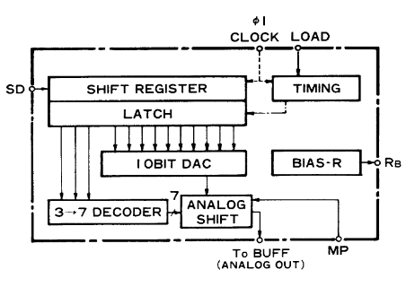
I wrote a small Verilog module to take the PCM sample data generated by this soft YM3812 and convert it to the unusual 3:10 floating point format required by the YM3014 DAC on my board. This is very similar to the operation of the real Adlib hardware, where the YM3812 generates and sends serial audio data to a YM3014 DAC chip. A modern I2S DAC may have been cleaner, but having a chance to play with the authentic DAC seemed a little more fun to me. All of this combined results in the same lovely crisp FM tones I was so fond of when I played games on my PC growing up.

The YM3014 uses a 10bit DAC feeding into a 3bit divider for more dynamic range.

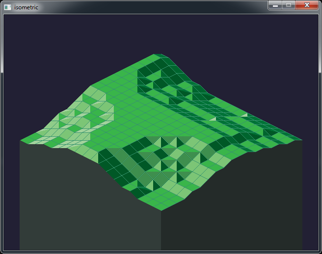
A lot of other elements of this project have been glossed over or omitted, such as support for CGA and EGA graphics. There is even a USB to UART bridge for sending files from a host PC directly to the SD card. I also made some nice clear acrylic panels on a CNC machine to round off the design and protect the bare PCB.

A video demo is shown below.
Unfortunately there is a ton of screen tearing due to the phase between the monitor and my camera. It isn’t visible in person.


Source code, schematics and gerber files are available on github here: https://github.com/bit-hack/iceXt

Thanks for reading!

Unknown's avatar

GD32 RISC-V Dev Board Pinout

This will just be a quick post to share my updated GD32 RISC-V pinout diagram. What makes this dev-board particularly interesting to me is the sheer number of GPIO pins and the fact that most of them are 5 volt tolerant which makes interfacing with older hardware really simple. The original pin-out diagram didn’t specify which pins were tolerant so I updated the diagram using the information in the datasheet for convenience.

Happy hacking!

Unknown's avatar

BulletHell Jam 2021 Entry

After a week of programming cursed C++ and OpenGL I have submitted my entry HARDPOINT to the itch.io BulletHell game jam as of last night. You can download it here and give it a shot yourself or just watch the video to see it in action below.

Some random technical takeaways from this jam in no particular order:

  • I really liked working with vector graphics for this entry. I would make 2D models in blender and then wrote a custom python script which would convert them from .obj into baked C++ source. This made it really easy to keep the graphics crisp, keep iteration times down and not require any external assets.
  • Finite State Machines are really great for handling game events that you want to be timed and animated. For example, when the player is destroyed the game state changes to handle that scenario. It pops up scroll text to the screen, waits for a period of time before re-spawning the player with a shield. FSM states can be chained too to produce more complex events like self destructing the boss, scrolling the background faster with a message, and then generating a new boss. I’m going to use FSMs a lot more in future game projects.
  • When dealing with rotations in 2D it is important to keep them all in the same representation if you can. I ended up with four different ways of representing rotations:
    • An angle as a floating point value (turned into basis using sin/cos)
    • A normal direction as a vector (where an orthogonal basis can be formed with its cross product)
    • Two vectors forming an orthogonal basis (lets you invert an axis to flip the handedness of the matrix)
    • A 4×4 matrix as used by OpenGL for transformations.
  • It was possible to convert between some representations and not others, and some representations might be more efficient for certain purposes. Trying to unify this would have lead to a lot less special case code and weird spaghetti code to work with the data in the way I wanted to. In the end the two-vector basis seemed like a pretty solid representation to pick. Every part of the boss for instance is represented by one plus and offset from the boss origin.
  • For a game jam don’t get too hung up on performance early on if its not a visible issue. This would be be bad advice generally there is only so much time you have available in a gamejam. One of the most inefficient parts of the code I wrote was the collision detection for player bullets and boss parts. I test every single bullet against every single boss part, which is an O(N*M) operation and scales terribly. I would rather have solved this by keeping an AABB tree for all of the parts inside “boss space”, transform each bullet into that space and test against the AABB tree. However… the performance seems really okay as it is and let me get on with other tasks, such as making the game more fun. If I saw any slowdown, then I might have tried to solve this issue.
  • I used SFXR for some of the sound effects which is really simple but generates so much aliasing I had to use a low-pass filter in audacity to tame it. Also beware that there is a bug in SFXR which will generate an incorrect .wav DATA chunk size when producing files at a sample rate of 22050. I wrestled with myself about fixing this issue, but lucky I made the right choice to just render at 44100 and move onto a more important task.
Unknown's avatar

BulletHell Jam Log1

I’ve decided to enter the bullet hell game jam currently running on itch.io and for the past few days i’ve been bashing out some trully gross C++ code.

My aim is to make a game simmilar to Warning Forever where the player is throw into a series of ever larger boss fights.

I spent most of yesterday working on procedurally generated bosses composed from various parts that can be destroyed. I didnt apreciate quite how complex the maths involved would be when it came to working out all of the rotations and collisions between everything which involved loads of 2D transformation matrix math.

Anyways here is a wee video of what I have so far in action. Its slowly turning into something interesting.

Unknown's avatar

Catmull-Rom Splines

I have been working on some code to generate procedural race tracks for a wipeout style game. Part of this work involved using splines to smooth out the track so it looks natural and curvy.

For this purpose I used a fourth order CatmulRom spline which has the nice property that its curve travels through the control points.

I also brushed of my high-school calculus and worked out a derivative function for the spline which is usefull for extracting normal vectors at any point on the curve.

// evaluate spine
// where t is between 0.f and 1.f
float catmullrom_spline(float t, float v0, float v1, float v2, float v3) {

  const float c1 = /********/    1.0f * v1    /*******/   /********/;
  const float c2 = -0.5f * v0 +  /*******/    0.5f * v2   /********/;
  const float c3 =  1.0f * v0 + -2.5f * v1 +  2.0f * v2 + -0.5f * v3;
  const float c4 = -0.5f * v0 +  1.5f * v1 + -1.5f * v2 +  0.5f * v3;

  return (c4 * t*t*t) + (c3 * t*t) + (c2 * t) + c1;
}

// calculate spline derivative
// where t is between 0.f and 1.f
float catmullrom_spline_deriv(float t, float v0, float v1, float v2, float v3) {

  const float c2 = -0.5f * v0 +  /*******/    0.5f * v2   /********/;
  const float c3 =  1.0f * v0 + -2.5f * v1 +  2.0f * v2 + -0.5f * v3;
  const float c4 = -0.5f * v0 +  1.5f * v1 + -1.5f * v2 +  0.5f * v3;

  return (3.f * c4 * t*t) + (2.f * c3 * t) + (c2);
}

The above code is only one dimensional but it can be fairly easily scaled up to two or more dimensions as follows:

// evaluate spline
// where t is between 0.f and 1.f
float2 catmullrom_spline(float t, float2 v0, float2 v1, float2 v2, float2 v3) {
  return float2{
    catmullrom_spline(t, v0.x, v1.x, v2.x, v3.x),
    catmullrom_spline(t, v0.y, v1.y, v2.y, v3.y)
  };
}

// calculate spline derivative
// where t is between 0.f and 1.f
// note that the return value will most likely need to be normalized.
float2 catmullrom_spline_deriv(float t, float2 v0, float2 v1, float2 v2, float2 v3) {
  return float2{
    catmullrom_spline_deriv(t, v0.x, v1.x, v2.x, v3.x),
    catmullrom_spline_deriv(t, v0.y, v1.y, v2.y, v3.y)
  };
}

Hopefully these functions are usefull to someone at some point.

Unknown's avatar

All things RISC-V

I have been increasingly interested in the RISC-V instruction set architecture recently and have undertaken a number of personal projects in this area.

For my initial foray into this realm I wanted to get my toes wet and decided to write an emulator for an RV32I processor, the base instruction set. The project quickly grew arms and legs and I had achieved much more than I thought I would at the outset.

The repository can be found here: https://github.com/bit-hack/riscv-vm

In its current state it is functions as a user mode emulator providing system call emulation which allows the virtualized processes to interact with the host OS. It passes many of the relevant RISC-V compliance tests and can even run an extensive set of benchmarks such as Dhrystone, Coremark, etc.

One of the most exciting features to me though, it that it can run Doom and Quake at decent speeds.

Seeing DOOM boot on your own VM is very satisfying.
QUAKE requires support for floating point arithmetic.

These two games were the most valuable benchmarks in terms of measuring execution speed, and initially they ran fairly slowly. DOOM was very easy to port as most of the hard work had been done as part of the DoomGeneric project. Quake however, required a fairly large amount of rework to build for my virtual machine which I spun off into its own project portable_quake which very much follows the principles of the DOOM port.

My pursuit of speed ultimately lead me to write an X86-64 JIT compiler for the VM allowing me to dynamically translate RISC-V code blocks into X86-64 code. This was a fascinating, rewarding and fairly complex process, but I learned a heck of a lot doing it which is always my main goal.

There is enough distinct topics in this project that I want to focus on them in more depth in following articles. The project is far from complete however and there are a lot of updates in the pipeline.

I also want to share some of the work I have done writing a tiny RV32I processor in Verilog to run on an FPGA using and OpenSource flow using Verilator, APIO and IceStorm.

Unknown's avatar

‘Surge’ for Ludum Dare 36

Last weekend I made spent 48 hours making a game from scratch for the Ludum dare game jam.  You can see the various videos I took during its development below (in reverse order of course :p).

surge

Binary available here: https://github.com/8BitPimp/ldjam/raw/release/ld36/surge.zip
Source: https://github.com/8BitPimp/ldjam/tree/jams/ld36

It was an absolute blast to make and I learned so much during the 48 hours of its development.

The game code was written from scratch in C++, the framework is based on SDL2, music was made in Ableton Live using an Amiga sample pack, pixel art was made with Aseprite and sound effects in SFXR.

Some key learning points were Finite state machines for enemy sequences.  Lissajou curves and hermite splines were used for some of the enemy and boss movement patterns.  I also had my first experience of using SDL_Mixer as an alternative to my usual choice of bass audio.

In the preceeding week, I had ducktaped together some of my previous small projects, so I was able to leverage a nice spatial hash implementation I wrote to handle all the collisions.  I also made use of a reference counted object library I made with an object factory and very simple RTTI.  These elements all worked as well as I could have hoped, requiring just a few tweaks during the compo.

I also think the vector version of the game looks pretty neat and could be and aesthetic worth exploring in the future.

Unknown's avatar

Quake 1 Palette Fun

Recently I have been playing around with the Quake 1 source, the SDL port [1] to be specific.  Quake was released in 1996 by id software as the highly anticipated successor to Doom.  It was also the first game of its kind to implement a proper 3d engine, quite a leap from the 2.5d engine of Doom et al.

screen5

One of the things that interests me about Quake is that it shipped with a highly optimised software rasterizer; and I have a weird facination with software rendering.  The quake source also contains a OpenGL rendering system, known as GLQuake, but I dont think the SDL port is quite setup to use it out of the box.

Internaly quake does all of its rasterization using 8 bit palletized colour.  While im sure this palette must be part of the games pak data files, it was simple for me to extract the pallette directly from quakes memory, as shown below:

quake_palette

Because each colour is represented as 1 byte, the pallette thus can only contain 256 entries.  Each colour entry in the pallete is stored as a RGB triplet, expanding each byte in the colour buffer to 24 bit true colour before its presented on the monitor.  The palette setup is done as follows:

// vid_sdl.c
void VID_SetPalette(unsigned char* palette) {
    int i;
    SDL_Color colors[256];
    for (i = 0; i < 256; ++i) {
        colors[i].r = *palette++;
        colors[i].g = *palette++;
        colors[i].b = *palette++;
    }
    SDL_SetColors(screen, colors, 0, 256);
}

Its clear just by looking at the screen shots that Quake has quite an advanced lighting system for the time, using lightmaps to store all of the incident light at each surface of the world.

Having the source to hand, one of the first things I wanted to do was to disable the surface textures so that I could view just the lightmap by itself.  As it turns out this was quite a tricky task, since Quake has to make a few interesting optimizations in this area.

// d_scan.c
// void D_DrawSpans8(espan_t * pspan) {
// ...
do {
    *pdest++ = *(pbase + (s >> 16) +
                         (t >> 16) * cachewidth);
    s += sstep;
    t += tstep;
} while (--spancount > 0);

Looking at the rasterization code above, which forms the inner loop of the surface rendering, it is apparent that only one texture is being indexed (pbase*), despite it being clear that each surface should be the product of the lightmap and the albido texture.  Its also clear in the above code that quake uses 16:16 fixed point arithmetic while indexing the lookup texture.

A little more digging reveales that once a surface has been deemed visible by quakes PVS System [2], it gets cached.  During this caching process, a new texture is allocated, which is indeed the product of the lighting contribution and the albido texture.

// r_surf.c
void R_DrawSurfaceBlock8_mip0(void) {
    int v, i, b, lightstep, lighttemp, light;
    unsigned char pix, *psource, *prowdest;
    psource = pbasesource;
    prowdest = prowdestbase;
    static const int STEPS = 16;
    static const int LIGHTMASK = 0xff00;
    for (v = 0; v < r_numvblocks; v++) {
        // FIXME: make these locals?
        // FIXME: use delta rather than both right and left, like ASM?
        lightleft = r_lightptr[0];
        lightright = r_lightptr[1];
        r_lightptr += r_lightwidth;
        lightleftstep = (r_lightptr[0] - lightleft) / STEPS;
        lightrightstep = (r_lightptr[1] - lightright) / STEPS;
        for (i = 0; i < STEPS; i++) {
            lighttemp = lightleft - lightright;
            lightstep = lighttemp / STEPS;
            light = lightright;
            for (b = STEPS-1; b >= 0; b--) {
                pix = psource[b];
                prowdest[b] = ((uint8_t*)vid.colormap)[(light & LIGHTMASK) + pix];
                light += lightstep;
            }
            psource += sourcetstep;
            lightright += lightrightstep;
            lightleft += lightleftstep;
            prowdest += surfrowbytes;
        }
        if (psource >= r_sourcemax)
            psource -= r_stepback;
    }
}

The function shown above is responsible for calculating the product of the light and the albido texture and writing that into the cached texture.  Looking at the inner most loop reveals that psource is the source texture itself and light is the lighting contribution for this texel.  vid.colormap is clearly some kind of lookup table used to combine the two attributes.

To test this out, I set pix to a fixed entry in the quake pallete and fired up the game, to see the following:

screen1

Nice! My hunch that pix was the source texture was correct, and now we are presented with only the lighting contributions.  One thing to note is that all dynamic objects in the world still appear textured, and this is because Quake has two rendering pipelines, the one for static BSP geometry that I have been playing around with, and one for dymanic models that I havent delved into yet.  That is yet another optimisation.

In order to learn more I dumped vid.colormap and wrote a quick program to transform it by Quakes palette and save it out as the image below:

quake_light_table

True to games of that era, its a lookup table containing pre multiplied versions of the base palette.  Such and aproach is necessary since we can easily transform from a 8bit colour index to the 24bit colour space that we would need to be in to perform our multiplication with the light, however its not possible to go back from a 24bit colour to the correct 8bit index.  By using a pre-multiplied palette we can effectively perform the multiplication, while staying in the 8bit colour index space.

If we instead set light in the above function to zero so that we are always indexing the top row of the colour table, we should render without any lighting contributions.

screen4

Another interesting point is that Quake also performs Mip Mapping [3], the bennefits of which are two fold.  Using smaller textures for far away surfaces reduces memory bandwith and uses less cache while also avoiding visual distortions caused by Alising.

This these changes must be made to each of the following:

// r_surf.c
void R_DrawSurfaceBlock8_mip0(void);
void R_DrawSurfaceBlock8_mip1(void);
void R_DrawSurfaceBlock8_mip2(void);
void R_DrawSurfaceBlock8_mip3(void);

When quake performs its caching, depending on the shape, size and slope of the polygon, one of the above functions will be chosen from a table of function pointers surfmiptable.

// r_surf.c
// void R_DrawSurface(void) {
...
if (r_pixbytes == 1) {
    pblockdrawer = surfmiptable[r_drawsurf.surfmip];
    ...
}


One fun modification that I wanted to make to the rasterizer was to add unreal style filtering [4] to quake, a challenge made more fun because it has to be done using 16:16 fixed point.  The block below shows the parts I changed:

// d_scan.c

#define DITHER 1

void D_DrawSpans8(espan_t* pspan) {
    
    // ...
    
#if (DITHER)
    int d_s, d_t;
#endif

    // ...

    pbase = (unsigned char*)cacheblock;

    // ...

    do {
        pdest = (unsigned char*)((byte*)d_viewbuffer + (screenwidth * pspan->v) + pspan->u);

#if (DITHER)
        // dither offsets
        d_s = ((pspan->v&1) << 16);
        d_t = ((pspan->u&1) << 16) ^ d_s;
#endif

        // ...

        do {
            // calculate s and t at the far end of the span
            spancount = (count>=8) ? 8 : count;
            count -= spancount;

            // ...

            do {
#if (DITHER)
                // compute dither offsets for texel
                int s_offs = (s - d_s + 0x8000);
                int t_offs = (t - d_t + 0x8000);
                // advance the dither pattern
                d_s ^= 0x10000;
#else
                int s_offs = s;
                int t_offs = t;
#endif
                *pdest++ = *(pbase + (s_offs >> 16) +
                                     (t_offs >> 16) * cachewidth);
                s += sstep;
                t += tstep;

            } while (--spancount > 0);

            s = snext;
            t = tnext;

        } while (count > 0);

    } while ((pspan = pspan->pnext) != NULL);
}

In the end it looks as follows:

screen2

screen3

This is a fairly dodgy hack to say the least as you can see we are reading +/-1 texels out of bounds around the edges of each texture.  It will require a bit more digging around in the source to correct this problem however.


If any of this was interesting to you, Fabien Sanglard has also written a fantastic teardown of the Quake source code [5].  He also must like the visual aperance of the Unreal texture filter and did something similar for Quake 2, see the end of this page [6].  You can see however that the original flipcode article contains a subtle bug however that is also visible in Fabiend’s screenshots.

The original flipcode article suggests a kernel which adds a small bias to the uv coordinates of half a texel which is undesirable:

          (X&1)==0        (X&1==1)
         +---------------------------------
(Y&1)==0 | u+=.25,v+=.00  u+=.50,v+=.75
(Y&1)==1 | u+=.75,v+=.50  u+=.00,v+=.25

A kernel such as the following should be roughly equivenant, yet adds no bias:

          (X&1)==0        (X&1==1)
         +---------------------------------
(Y&1)==0 | u+=.5,v+=.5  u-=.5,v+=.5
(Y&1)==1 | u-=.5,v-=.5  u+=.5,v-=.5


[1] The SDL port was written by Sam Oscar Lantinga, the author or SDL and can be found here: https://www.libsdl.org/projects/quake/

[2] Potential Visibility Set: http://www.phatcode.net/res/224/files/html/ch70/70-02.html

[3] Mip Mapping: https://en.wikipedia.org/wiki/Mipmap

[4] Unreal style filtering: http://www.flipcode.com/archives/Texturing_As_In_Unreal.shtml

[5] Quake source code review: http://fabiensanglard.net/quakeSource/index.php

[6] Quake 2 rendering: http://fabiensanglard.net/quake2/quake2_software_renderer.php

Unknown's avatar

random.h

random.h is a header only random number generation library for games, image processing and procedural content generation.

A few years back I wrote some handy floating point random number generation routines for a raytracer.  Time and again, I have needed these routines for other programs I have been working on.  It seems like a good idea to wrap them up in a small header and release them in the public domain for others to use too.

Each RNG function takes an 64bit integer as a seed value and permutes it in place.  The resulting bits are used for the generation of the result.  I like this design as it keeps the RNG functions stateless and thread safe.  You just have to keep track of the uint64_t you have been using as your RNG stream.

Included are various 1, 2 and 3 dimentional random number generators with a range of different distributions.

Triangular random noise is very usefull when dithering audio and images during the process of bitdepth conversion.  Typicaly, triangular noise is added to the signal immediately before type casting (at the same magnitude as the LSB of the destination bit depth).

The 2d and 3d vector RNG functions generate statisticaly unbiased vectors inside and on the unit circle or sphere (Generating vectors by randomizing the components and normalizing would bias the vector to the corners of unit cube).  I have used these functions successfully in the past for generating ambient occlusion maps.

I wrote a little program to generate some images to display the output distribution of each function.  A 3d point is generated by filling its component from the RNG function under test, and the resulting point is projected in space, as well as projected on each component axis (the red, blue and green planes).  Hopefully the images help a little to convey the distribution of each function.

Again, you can find the library here:
random.h

randfu() - unsigned random 
range [0,1]

randfu_2

randfs() - signed random 
range [-1,+1]

randfs_2

trandfs() - triangular random 
range[-1,+1], tends to 0

trandfs_2

grandfs() - gaussian random 
range ~[-1,+1], tends to 0

grandfs_2

vrand3d() - 3d vector random 
magnitude range: [0, 1]

vrand3d_2

nvrand3d() - normalized 3d vector random 
magnitude = 1

nvrand3d_2

vrand2d() - 2d vector random
magnitude range: [0,1]

vrand2d_2

nvrand2d() - normalized 2d vector random
magnitude = 1

nvrand2d_2

Unknown's avatar

Binary Heap

Despite lack of activity here I have been very busy programming cool stuff which I hope to get around documenting and sharing with you all.

I need to implement the A* algorythm for one of my projects. Its a fairly common to speed up of the implemention to use a binary heap for the open list because of its O(log(n)) insertion and O(1) removal properties.  As I code it up I thought it would be nice to share my binary heap implementation, something which can be a bit fiddly to get right in practice.  I wrote a little fuzz tester to nuke it, so that I can be fairly sure it works correctly.

Gist: BinaryHeap

I chose to make the size fixed at compile time for simplicity, and becaues I am happy to terminate a pathfinding search that exceeds a fixed open list size, as old school games used to do.  It should however not require much work at all to grow the heap size when a node is pushed when currently at full capacity.

I will also leave you with this picture from my latest project:

isometric